Predicting Coverage with Radio Mobile

Radio Mobile is a free tool created by VE2DBE that can be used to predict radio wave propagations and plot them on maps. Radio Mobile uses basic topographical data combined with some vegetation clutter data to predict radio wave propagation. Some skill is required to generate accurate predictions, but using this guide will get you pretty close.


Introduction

Essentially what this tool allows you to do is create two “imaginary” radio stations, and calculate which places these two stations will be able to send/receive signals between each other.

For example, lets say that station (A) is a base radio with an external antenna at your house, and station (B) is a mobile (vehicle) radio. Radio Mobile will let you generate a map overlay that visually projects where (A) and (B) will be able to talk to each other.

The settings used in this guide are the exact settings that were previously used to generate coverage models for repeaters in the Arkansas GMRS Repeater Group, and are at least somewhat “verified” to be accurate.

Radio Mobile uses very basic terrain & vegetation clutter data. It does not use any data for buildings or structures. Densely urban propagations will not be accurate. Vegetation data may be out of date. There are more accurate professional & commercial tools, but Radio Mobile is widely recognized as one of the best free propagation prediction tools available.


Step by Step

  1. Start by entering the Radio Mobile website.
  2. Create an account or login.
  1. Click New Site, and place the pin at the exact location of wherever you want your base / repeater station (A) to be.
  1. Click Submit, and give the site a name. I will call mine “Repeater”.
  2. Click Add to My Sites to save it.
  1. Click New Coverage.
  2. Select the site you just created (“Repeater” was used above)
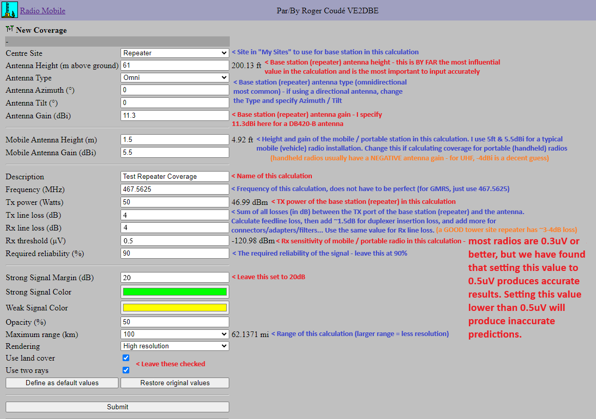
  3. Set all variables as accurately as possible.

It is very easy to generate a coverage prediction that far exceeds how the system would perform in real life. If you are estimating or do not know the exact value for a given field, try to be conservative with your estimations. When in doubt, estimate the system to be worse than you expect, so you do not end up with an over-confident coverage prediction.

  1. Wait for the calculation to finish (it might take a while)
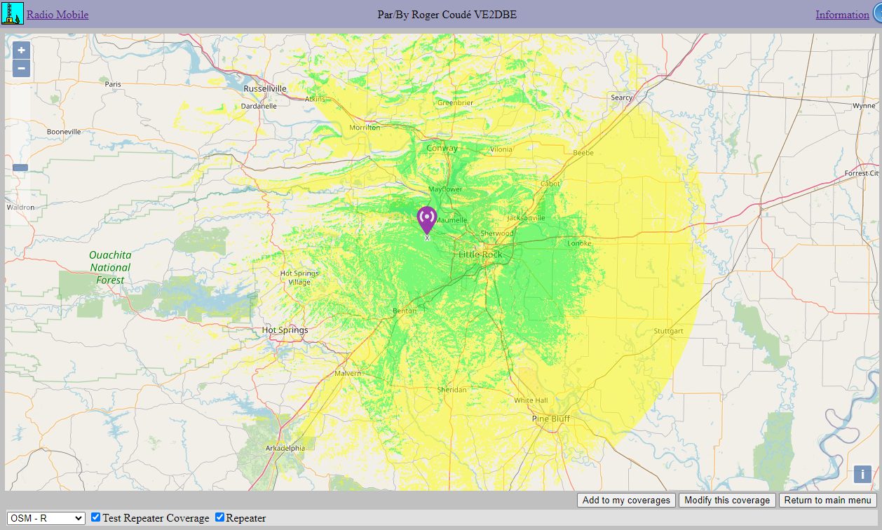
  2. Browse the predicted coverage map. Click Add to my coverages to save this calculation for later viewing.


Antennas for All – An introduction to Antennas

You can have the best radio in the world, but it doesn’t mean anything if it doesn’t have a useful antenna on it.

Let’s say you are new to GMRS and all you have is a handheld (HT) radio. Immediately what most do is to try to figure out the range of their signal. They may be able to go a couple miles, but soon they realize that they aren’t using the full extent of their license and making the most of their radio system. They might look to improve- and that’s what this article is for.

The antenna summarized in a word would be COMPROMISE. It’s a compromise among a number of considerations, such as budget and spousal approval. Nevertheless the best improvement one can make to their station today – as a HT user – and tomorrow as a proper 50 watt repeater and 200′ tower – is to improve what antenna they use.

The concept is pretty simple. An antenna put out energy (it “radiates”) in almost all directions. In fact the ideal antenna radiates energy in all direction, but as you can imagine such an antenna exists only in text books. Here you can see the source being the red dot in the middle, and the wire mesh is the radiated power. If this is a bit confusing, just hang in there.

The most iconic antenna is the Dipole. It is a fundamental building block to other designs. A Dipole is 1/2 wavelength long, which at GMRS Frequencies is about 12 inches. This is what it’s pattern looks like:

You can see the radiation pattern in the bright red ring. It very much looks like a donut shape. The dipole would run through the hole of the donut. You’ll also see two cross sectional pictures – the Elevation and the Azimuth.

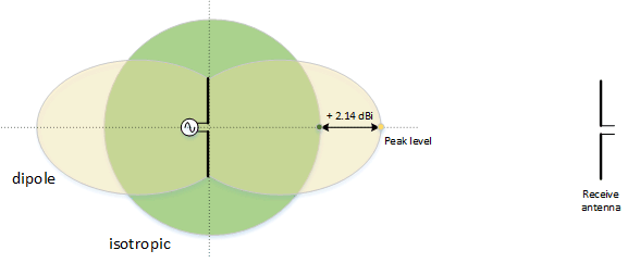
You can see now that we went from a perfect sphere to a donut. This squashing and changing of the antenna radiation pattern is what makes or breaks an antenna. It’s also why there are so many weird and odd designs for antennas. Here’s a comparison of the two if we overlay a cross sectional look:

You can see where the green gets “smushed” down to make it go more out horizontally. For us this is a good thing. Usually the people or repeaters we want to talk to are at the horizon. There are other antenna designs that smash this even flatter, which we will look at shortly.

The dipole is also known as a “1/2 wave antenna” if you look up a mobile version. Many times mobile stations will use 1/4wave antennas. The patterns are similar as electrically with a ground plane of a car, they work much like a dipole.

~Which brings up a good point, without enough ground plane for an antenna to “work” against, you are essentially cutting your antenna in half.~

So with this idea of smashing down the donut, you can even make it flatter into a pancake. So unless I’ve lost you, you can make your power go from a ball to a donut to a pancake. You can even “stack” these antennas, which is to say put more together. For example, the go to common repeater class antenna is the DB420 antenna, made by Decibel (or who ever owns it this week). This antenna has 16 dipoles mounted on a 20 foot long pole with a gain of 11.3dBi (dBi means the number of dB over an isotropic antenna) this means you signal is ~15.2 times as powerful out on the horizon then our simple little perfect ball. It also means that it is ~9.15dBd (dBd means the number of dB over a dipole, the only practical reference antenna). In these terms, that means that the signal is about 8.5 times stronger at the horizon than the dipole.

So let’s step back and think about this for a minute. Let’s say I’m running 5 watts into a DB420 repeater antenna (we’ll just ignore feedline loss, that’s for another article.) In order to get that same radiated power (i.e. coverage, distance, etc.) while using a dipole, you would have to transmit 42.5 Watts.

This isn’t magic or free energy. This is just moving around the part of the radiated signal into a more useful direction.

In the next article of Antennas for All we are going to move away from theory and talk more about choosing which to build or buy.